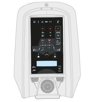
MTP23X and MTP33X control panels include physical push buttons for the most common setup and adjustment features as well as a small digital display for showing the adjustment values and more in-depth settings.
MTP23X control panel has only the DC current mode available
Controls:
The MTP23X control panels are used with a control knob and with two function buttons in the bottom section of the front cover as well as with dedicated push buttons on the panel itself. The control knob can be turned and used also as a push button according to the current selections. Settings and adjustment values are shown on the digital display embedded in the control panel.
1.Control knob
•
In home mode this adjusts the welding current (A)
•
Used to navigate within the control panel's embedded display and settings
•
When the green light is lit in the knob center, the knob also functions as a push button for selection
2.Welding process selection button (left function button)
•
Switches between welding processes: TIG / MMA
3.Welding mode selection button (right function button)
•
Switches between welding modes: Continuous / Spot / MicroTack
•
Short press switches between current modes: AC / DC- / Mixed current (AC/DC-)
•
Long press switches to DC+ mode
5.Ignition mode selection button
•
Switches between different ignition modes: Lift TIG / High frequency (HF) ignition
6.Trigger logic selection button
•
Switches between the trigger logics: 2T / 4T
7.Pulse mode selection button
•
Selects the pulse mode or turns the pulse off: Auto / Manual / Pulse off
8.Gas test button
•
Flushes the gas line without ignition and welding
•
Pressing the Gas test button starts the gas test with default time. Gas test time can be adjusted by turning the control knob (1) during the gas test: 0 s ... 60 s, step 1 s (Default: 20 s)
•
Gas test can be stopped by pressing the button again.
9.Start & stop sequence button
•
Toggles between Start & stop sequence settings: Pregas / Upslope / Hot start level / Hot start time / Minilog (4T only) / Downslope / Postgas
•
If AC mode is on, AC frequency and AC balance settings can be accessed
•
If Pulse mode is on, Pulse current, Pulse ratio, Base current and Pulse frequency settings can be accessed
>> In the Pulse Auto mode, these settings can be viewed only.
10.Settings button
•
Opens the settings menu
•
Advanced settings can be accessed with a long press of the button.
Settings menu content depends on the currently selected welding process and mode.
11.Home button
•
Returns you to the initial work mode where the welding current (A) can be adjusted
Lights and symbols:
a.Cooling unit
•
Green: Cooling unit is connected and running
•
Red: Cooling unit is connected, but there is a problem (e.g. with coolant circulation)
b.Operating temperature
•
Yellow: Welding equipment has overheated
c.General notification
•
Yellow: There is an error that requires attention
•
Red: There is a fault that prevents welding
•
The error code is shown on the display. If the error does not prevent welding, this error code can be dismissed, but the notification light stays lit.
d.VRD (voltage reduction device)
•
Green: VRD is on
•
Red (blinking): There is a fault with VRD that prevents welding
•
Not lit: VRD is off
e.Wireless device
•
Blue: Wireless device is connected
•
Blue, blinking: Pairing in progress.
In error situations, an error code is displayed. Refer toTroubleshootingfor more information on the error in question.